Timing devices" is a new approach to brain science, based on a new technology.
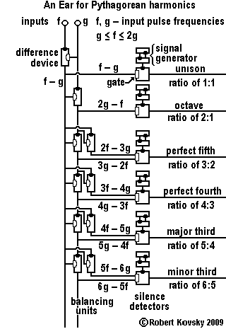
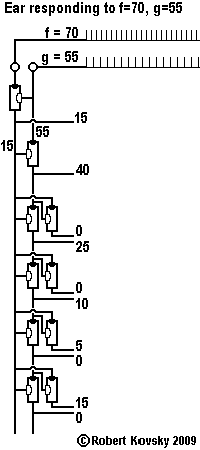
An Ear for Pythagorean harmonics is a device design that shows how timing devices can imitate brain functions. The design for the Ear is shown in the adjacent image and discussed on this page. In operation, the Ear detects when two input signals f and g, "pure tones" musically, are in a relationship that is known as a "Pythagorean harmonic" (octave, perfect fifth, major third, etc.). When a harmonic relationship is detected, a signal appears on the output line bearing the name of the harmonic. A frequency combination shown on an internal line, e.g., |
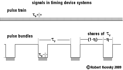
The two chief types of signals in timing device systems are shown in the adjacent image: uniform pulse train and pulse bundles. |
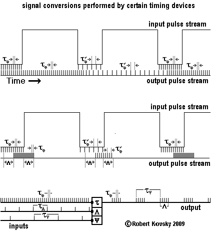
Some timing devices operate with pulse trains and other timing devices operate with pulse bundles. Certain timing devices convert signals from one form to another. The adjacent image shows three examples of conversion. The top two images show inputs and outputs of two kinds of "streaming devices" and the bottom image shows inputs and output of a "pulse bundle generator." (Please see Figures 26, 28 and 29, respectively, in the technical Timing Devices paper.) |
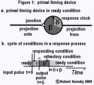
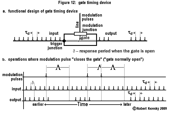
The primal timing device has a "response clock" that is like a stopwatch used in sports contests, shown in Figure 1.a as a circular clock dial. Two projections connect the primal timing device to other timing devices and a junction connects the "projection onto" to the response clock. A pulse arriving at the junction through the projection onto starts the "response process," which runs through a cycle of conditions, during which the primal timing device discharges a pulse through the "projection from." As shown in Fig. 1.b, a primal timing device has a "ready condition," a "responding condition" and a "refractory condition." The device responds to an arriving input pulse only when it is in the ready condition. Suppose an input pulse reaches a ready device at time t = 0, initiating the response process. The response clock starts and the device enters into the responding condition. At t = δ, the device discharges an output pulse through the projection from; and the device enters into the refractory condition, which continues until t = δ + β, when the device enters into the ready condition, completing the response process. |
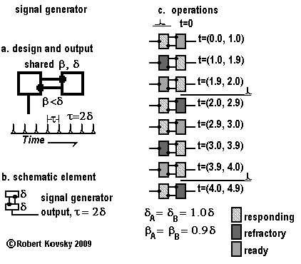
Two inter-connected primal timing devices function as a signal generator, as shown in the adjacent images. Image a shows the design and output of the signal generator. The design resembles that of a multivibrator in standard electronic circuits. Image b shows a schematic element that is used in the design of the Ear for Pythagorean harmonics. Image c shows the signal generator in operation. An initiating pulse arrives at time t=0. Thereafter, the assembly goes through changes in an orderly way, represented by a sequence of momentary images, like frames in a video. Conditions of timing devices last for a specified period of time stated as t=(a, b) in each momentary image. In the idealized operations of timing devices, conditions change instantaneously. The images show conditions "before" and "after" each change; but the changes themselves are not shown. However, the discharging of pulses is pictured as taking place during changes that occur at t=2δ and t=4δ. |
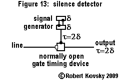
Figure 13 shows the design for the silence detector that is used in the Ear for Pythagorean harmonics. The silence detector is assembled from a signal generator and a normally-open gate timing device. In the silence detector, the normal condition of the gate timing device corresponds to silence on the line to the gate. When there is such silence, the gate is open and the signal from the signal generator passes through to the output. On the other hand, when pulses arrive regularly through the line onto the modulation junction of the gate, the gate will stay closed. Then there is no output. In brief: a signal on the line means a silent output. Silence on the line means that a signal from the signal generator appears as the output of the silence detector. |
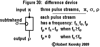
Figure 30 shows the design element for the difference device and its operations as a frequency subtraction device.
There are three signals: pulse streams π, σ and ρ. Pulse stream π is the input to the difference device. Pulse stream σ - called the "subtrahend" - resembles the stream of modulation pulses to the gate timing device but with somewhat different effect. Here, each pulse in the subtrahend stream cancels one pulse from the input stream. Pulse stream ρ is the resulting output stream.
Operations require that "defined" pulse streams arrive through the input and subtrahend lines. A defined pulse stream need not be perfectly uniform; it is sufficient if a specific pulse frequency can be assigned and if irregularities "holes" resulting from cancellations are smoothly distributed. These requirements are met for operations of the Ear for Pythagorean harmonics.
A defined pulse stream has a specific frequency and the following relations describe the operations of the device.
|
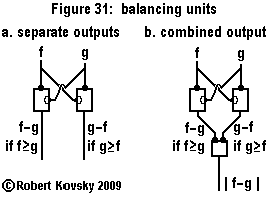
Figure 31 shows an important use of the difference device, in two versions of "balancing units." In each version, two difference devices are hooked up to two pulse streams (f and g) that serve as input and subtrahend, one each to each difference device. For two defined input pulse streams, no more than one difference device will be operating at any given moment and its output line will be carrying a signal; the other difference device will be silent. If the two pulse streams are identical (or nearly so), both lines will be silent.
Figure 31.a shows a balancing unit with separate outputs.
In the balancing unit shown in Figure 31.b, the outputs from the two difference devices are inputs to a simple timing device. At any moment during controlled operations, no more than one difference device generates input to the simple timing device and the simple timing device responds like a primal timing device. The possibilities are combined in the formulation |
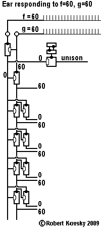
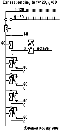
The adjacent images show the Ear operating at the limit points of its range of operations. At one limit point of the range of operations, when f=60 and g=60 and the two inputs are "in unison," the Ear detects that fact and a signal appears on the "unison" output line but on no other output line. The image for f=60, g=60 shows only the single silence detector where the gate is open. Its modulation line is silent; the frequency of the signal to the modulation junction is 0. The other image shows operations at the limit point that is the polar opposite of the first, that is, when f=120 and g=60 and the relationship is "octave." Again, that fact is similarly detected and a signal appears on the "octave" output line but on no other output line. In each image, the frequencies of the paired outputs of the balancing units at levels below the octave all have the same values. The frequencies of those paired outputs when the inputs are f=60, g=60 are reversed from the pairs when the inputs are f=120, g=60. As f traverses its range, moving from 60 to 120, the paired frequencies shift in an orderly but complex fashion from one extreme to the other. |
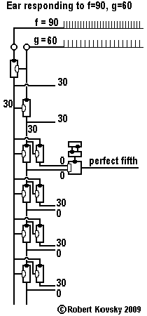
The adjacent images show operations of the Ear at intermediate points in its range of operations. When f=90, g=60, the relationship between the input tones is that of a "perfect fifth," as detected by the Ear. Both inputs to the perfect fifth silence detector are silent. The ratio is |
Your comments and suggestions are welcome. Please write to the adjacent email address (shown in an image to minimize spam). |
2/26/11