Viewed from an alternative approach, an Eye for Sharp Contrast offers numerous opportunities for improvement and development. This page proposes some improvements and possible developments.
As a place for ongoing development, this page is subject to supersession. The present first publication identifies matters for further detailed development.
( ... ) Link List
( ... ) top of page
Frequency multiplication of the edge signal.
In present designs of the Eye for Sharp Contrast, a large amount of time is spent "waiting" for a possible output signal from the comparison unit. The wait is needed to detect a low frequency signal. To detect a signal with 2 to 3 pulses per second requires .33. sec to .5 sec. for assured detection.
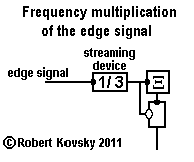
| It is possible to insert a frequency multiplication device in the line carrying the edge signal to the comparison unit, as shown in the adjacent Figure. A 3-to-1 multiplication is proposed. Suppose that during operations the edge signal goes down from 19 pulses per second in one cycle to 17 pulses per second in the next cycle, a difference of 2 pulses per second that should be detected for successful performance, requiring 0.5 sec. to detect with assurance. When the edge signal is multiplied by 3, the resulting frequencies are 57 pulses per second and 51 pulses per second, with a difference of 6. Only .17 sec. is required to detect this signal with assurance, a third of the value without the frequency multiplication device. |

|
An appropriate frequency multiplication device is a ( ... ) streaming device from the Kit of Parts. The desired streaming device has a specification of 1/3. This means that the input signal is treated as a succession of periods between pulses. The most recent input period is the time interval between the most recent input pulse and its predecessor. When a new input pulse arrives, a new most recent input period is determined. The output period is based on the most recent input period. When an output pulse is discharged, the device sets the period to the next output pulse discharge and that period is 1/3 of the most recent input period.
The effect of the 1/3 streaming device is to produce an output signal with a pulse frequency that is three times that of the input signal.
Use of the 1/3 streaming device requires adjusting the system to meet increased demands. The maximum edge signal is 33 pulses per second, based on a juxtaposition of the two end-of-range limit points of sensorial response, dark and bright extremes. That is, the maximum edge signal, 33 pulses per second, is a difference signal produced from two sensory-modulated signal generators generating 17 and 50 pulses per second respectively. Multiplying that maximum edge signal by 3 produces 99 pulses per second.
The maximum carrying capacity of a timing device where δ = δ0 and β = 0.1 δ0 is 1/(1.1 δ0); in the case where δ0 = 0.01 sec., the maximum carrying capacity is about 90 pulses per second. However, another standard timing device specification used in the Eye for Sharp Contrast is δ' = 0.8 δ0 and, for such a specification and the same β, the carrying capacity is 111 pulses per second, sufficient for operations using 3-to-1 frequency multiplier.
The improvement requires additional modifications in other parts of the system, e.g., to the Ξ bundle storage device.
( ... ) top of page
Bursting timing devices.
The bursting timing device generates a number of pulses with a very short period between pulses. In a specific proposed design, pulses are produced at a rate of 4 per δ in a burst of up to 16 pulses. Bursting timing devices use a different way of organizing response periods and refractory periods. In the bursting timing device, there still a response period between the arrival of a trigger pulse and the first pulse of a burst; but there is neither response period nor refractory period for later pulses in the burst. A single long recovery period occurs after all the pulses in the burst. The single long recovery period plus one responding period is equal to the sum of the response periods and refractory periods for all the separate pulses.
The principles that govern the bursting timing device are those discussed in the Quad Net Model. The principles involve "virtual energy." A steady stream of virtual energy fuels the operations of each timing device. If a timing device operates with δ = 0.008 sec. and β = 0.001 sec., as in the original Bundle Cycler, enough virtual energy flows into a device in 0.009 sec. to generate a pulse. In the primal timing device, there is only enough storage for one pulse; energy arriving after the first 0.009 sec. is dissipated. For 16 pulses, .144 sec. is required. The bursting timing device has enough storage for 16 pulses and 0.144 sec. are required between bursts so that this storage can be filled if necessary. Because one response period is still required to generate the first pulse after the arrival of the trigger pulse and because the signal bloc of 4 δ is separate, the recovery period for the bursting timing device is 0.144 sec. and the minimum cycle period is 0.184 sec. If the period between bursts is more than 0.184 sec., the excess time is spent in the "readiness" condition.
The bursting timing device suggested here has a counter that enables it to discharge the same number of pulses as it receives. A more complex bursting device generates a variable number of pulses that is controlled through an additional input.
The chief advantage of the bursting timing device is finer control over activity of muscle fibers. Multiple bursting devices can stimulate a single muscle fiber, which can be re-configured for faster response and smaller twitches. A second finer system can be interwoven with the first coarser system. Having two systems provides possibilities for enhanced control and for combinations.
( ... ) top of page
Echelon design for the Bundle Cycler.
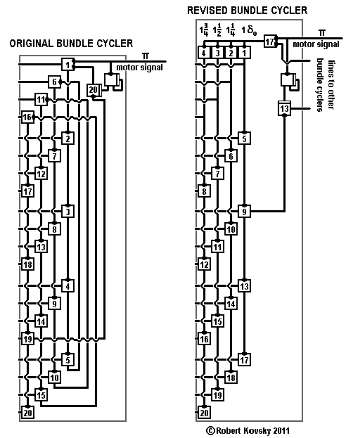
The Figure below shows a revised design for the Bundle Cycler. The purpose of the revision is to enable faster muscular response; new motor signals can be introduced more quickly, almost four times as fast. The design employs bursting timing devices.
The proposed system uses four of the revised bundle cyclers. The four cyclers are themselves connected in a cycling way through links involving "unattached" projections from timing devices 13 and onto linking timing devices 17, which serve as circulation connectors. Alternative operations allow for slow changes with a single motor signal input and sequential transmission through 4 bundle cyclers or for fast changes with a fresh motor signal seizing control of all bundle cyclers in one swoop. Using figures from the discussion on bursting timing devices, fast changes can occur four times in 0.184 sec. or about every 0.046 sec., equal to about 6 δ..
( ... ) top of page
Development of the Edge Detector.
The Edge Detector has potential for development in several directions.
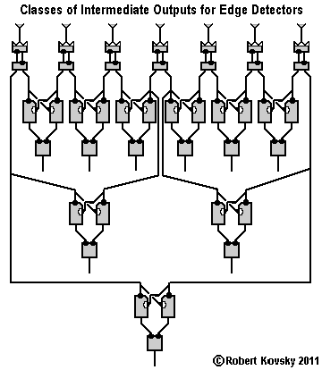
| As shown in the adjacent Figure, Intermediate Outputs can be generated that are additional to those in the original Edge Detector. Classes of Intermediate Outputs are generated simultaneously and may be useful in controlling operations. |
| As shown in the adjacent Figure, an Edge Detector can be symbolized and viewed as two "sub-parts" connected through Intermediate Outputs. The "primary sub-part" contains the light-sensing devices and generates Intermediate Outputs. The "secondary sub-part" receives Intermediate Outputs and generates the edge signal. Edge Detectors and sub-parts become units in various possible constructions. |

|
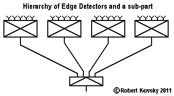
| In the assembly shown in the adjacent Figure, Edge Detectors generate edge signals and the edge signals function like Intermediate Outputs that are received by the secondary sub-part. The result is a hierarchical structure that can be extended for an indefinite number of layers with controllable interfaces between levels. |
|
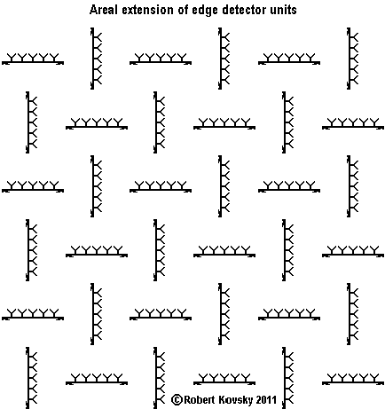
The adjacent Figure shows development of the Edge Detector into a two-dimensional area. Edge Detectors and/or sub-parts are alternatively oriented in horizontal and vertical directions. Construction methods can potentially combine classes of Intermediate Outputs, hierarchical processing and two-dimensional configurations.
|
|
( ... ) top of page
Hierarchical vs. Quad Net sensory systems.
No content at this time.
( ... ) top of page
Saccadic (jumping) activity of the Level Shifter.
No content at this time.
( ... ) top of page
Detection and following of transverse motion and perhaps color.
No content at this time.
( ... ) top of page
Simultaneous operations using multiple capacities.
No content at this time.
( ... ) top of page
( ... ) top of page
|
Your comments and suggestions are welcome. Please write to the adjacent email address (shown in an image to minimize spam). |

|
2/5/11