Wriggler Projects
- 1. Wriggler I: an engineered organism (2020)
-
a. ... discussion
b. ... condensed version of the construction
c. ... download full report in .pdf format (2.8 Mb)
- 2. Metamorphosis of Wriggler I (2021)
-
a. ... discussion
b. ... download full report in .pdf format (1.3 Mb)
- 3. Wavy movements in a hybrid domain of classical and Virtual Energy devices (2022)
-
a. ... discussion
b. ... download full report in .pdf format (3.3 Mb)
- 4. Reconstruction of the Wriggler I system for quicker, more compact operations (2022)
-
a. ... discussion
b. ... download full report in .pdf format (770 kb)
Wriggler I: an engineered organism (2020)
|
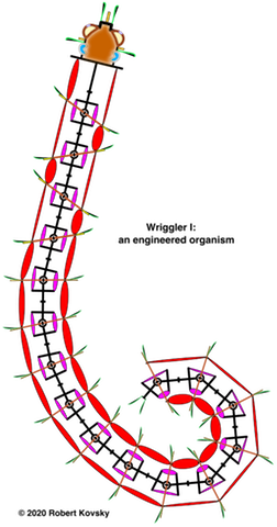
In anticipated operations, Wriggler I moves on the bottom of a water-filled tank, such as an aquarium. Multiple kinds of movements can be commanded by harmonic sequences (musical chords) and influenced by visual and tactile objects and by internal bodily conditions (stretches, stresses). Long-range goals of the project include engineered organisms (wrigglers) that resemble animals foraging in a risky environment, with wide-ranging capacities for producing and adjusting movements on the basis of multiple influences.
The initial project constructs a simple and limited kind of movement called remotely-controlled movements. These "remote" movements resemble certain movements of robots and are represented by math-like structures, although the proposed technologies and the representations are fundamentally different from computational versions. A condensed version of the construction is set forth below (...).
Rather different residential movements are developed in "Wavy movements in a hybrid domain of classical and Virtual Energy devices" (2022) discussed below.
Devices in proposed technologies operate according to new "rate-based" Virtual Energy (VE) principles where flows of VE have a character like flows of blood sugar in animal bodies or flows of electricity in electronics devices. Instead of stored bits of data as in computers, storage bodies contain VE. Controlling forms are based on time units of muscle-like twitches that resemble beats in music. A new kind of code controls discharges of VE and productions of movement; and the code resembles a musical score rather than a computer program. Strengths and timings of movements are signaled by instantaneous pulses – idealized versions of action potentials in animal nerves. Each pulse carries one unit of VE, called a bang and denoted by !.
The ultimate aim is to build engineered organisms that exercise freedom. Anticipated exercises of freedom embody a physical principle called Shimmering Sensitivity that I suggest can operate in networks of VE devices during a critical moment – when many possible movements change into selected actual movements. It's like picking a candy bar from a rack of snacks in a store. Many influences converge during a momentary transformational event, during which ... possibility ... turns into ... actuality.
|
|
... top of page
Metamorphosis of Wriggler I (2021)
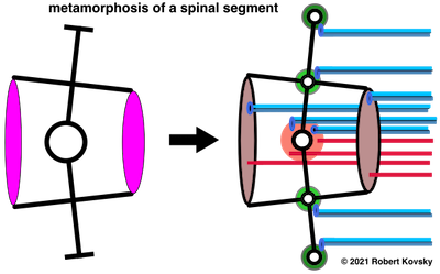
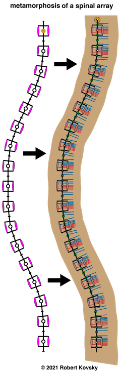
The images show changes in a spinal array from the prior Wriggler I project, plus an enlarged exemplary spinal segment. In contrast to "remotely-controlled movements" investigated in the prior project, goals in this project were body based "residential movements," especially "wavy movements" like those of worms and eels.
This project fell short of the goals. Certain "wavy movements" are produced by designs in the next project discussed below.
|
Both spinal arrays are in the shape of a waveform with a wavelength of 16 segments. Arrays have 17 segments for visual completion. A waveform guides production of wavy movements but changing shapes of a moving array differ from a stationary waveform. E.g., forces in a waveform are in equilibrium while those in a moving array are not..
As shown in the enlarged version, a new pair of annular movers encircles the central hub of a spinal segment, producing forces like those produced by the exterior movers carried over from the prior project. Forces from two pairs of movers can be added, subtracted and/or coordinated. To produce faster movements, movers are further multiplied in number and overdriven with expanded force differentials.
Red projections (lines) carry drive signals to movers. Two coupled blue projections carry sensory signals from movers, denoting the length of a mover and changes in a mover's length. Such signals resemble signals produced by sensors in animal muscles that participate in proprioceptive functions.
Elastic joints, shown as green discs, replace rigid joints. Energy storage and release in elastic joints produces smoother movements. Blue sensors in elastic joints detect stresses (measured as deviations from equilibrium positions) and changes in such stresses.
A complete set of projections connects to control systems that reside in the body of the organism and that depend on the body (shown in brown). A duplicate set of projections connects to remote control systems in the head.
|
... top of page
Wavy movements in a hybrid domain of classical and Virtual Energy devices (2022)
Remotely-controlled or "remote" sequences of movements produced in the Wriggler I project occur under specific temporal restrictions that I call detached time. The speed of a movement does not affect the sequence of movements or the final result. Interruptions and postponements are easily accommodated. An example of detached time movements in ordinary human activities occurs when we put dishes away after washing and drying. Dishes are moved from the drying rack to the cupboard in separate movements. Each movement can be fast or slow. The anticipated sequence of movements can be interrupted or postponed at any point between movements, e.g., if the phone rings. None of the variations affects the final result.
In contrast, an action game like ping-pong cannot be described or modeled by remote movements. Timing of actions is the essence of the play and sudden movements involve the whole body from toes to fingertips. A small postponement will lose a point. It appears that naturally-occurring interactive changes and movements of material bodies occur in a common and shared actual time, including movements of human bodies that are playing ping-pong.
Timing in Virtual Energy models is based on temporal restrictions called controlled time. Musicians are familiar with controlled time, measured by the number of beats per minute on a metronome. It is possible for an orchestra to play the tune faster or slower if all parts change together. The controlling conductor beats the time. An individual performer, e.g., a pianist, exercises personal freedom by varying the tempo to suit their mood. I suggest that Virtual Energy models operating in controlled time can not only produce detached time movements (as in Wriggler I), they can also mimic certain movements of animal bodies that occur in actual time. This "wavy movements" project constructs a controlled-time domain for investigation of such movements, such as squeezing and stretching movements of an earthworm.
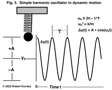
| In a physics paradigm called the Simple Harmonic Oscillator ("SHO") (Fig. 3), timing of movements depends on the stiffness k of a spring and the mass m of an attached ball. The ball moves in repetitive oscillations. Each cycle takes a period of time called Τ and Τ2 = (2π)2 x m/k. We control Τ by varying m and/or k.
|
|
|
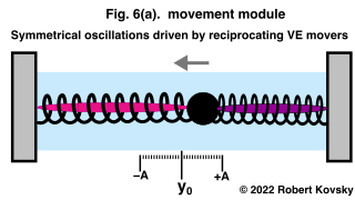
The SHO is further developed in the movement module of Fig. 6, where twitching muscle-like movers pump energy into the ball and keep it in steady oscillatory movements despite dissipation resulting from movement through a surrounding viscous fluid. In Fig. 6, the actively-twitching mover is bright magenta while the flaccid inactive mover is dull purple. A twitching mover has 15 possible levels of force and the amplitude of repetitive symmetrical oscillations has 15 possible values.
|
|
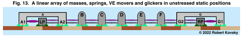
In the more advanced design in Fig. 13, masses ride on green glickers that have two states: (1) a light green gliding state where the mass slides without friction on the track; and (2) a dark green sticking state where the mass is fixed immobile to the track and no force can dislodge it. In the Fig. 13 design, the array moves by means of mover twitches and switching glicker states. Multiple repertoires of movements can be produced. In controlled-time operations, some movements have detachable aspects and others are continuous.
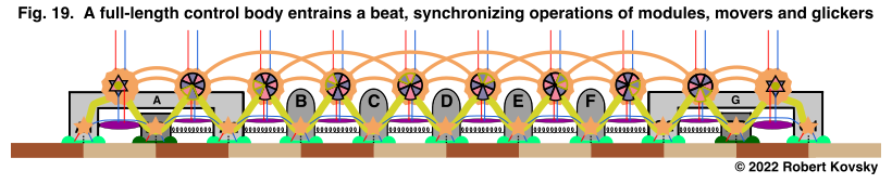
Designs in this project are constructed in a domain defined by classical physics, along with augmentation from Virtual Energy movers. Anticipated further developments are concerned with a VE domain occupied by VE bursters, modules and control bodies that drive the movements. Fig. 19 suggests lines of development. Whole-body operations are maintained by the full-length yellow sinuous body that entrains a synchronizing beat.
full-size image: (...)
... top of page
Reconstruction of the Wriggler I system for quicker, more compact operations (2022)
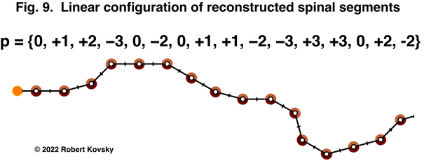
Innnovations in previous projects are developed and combined in new constructions. Development aims for simplification and quickening using reconstructed device parts. The number of stationary positions of a spinal segment is reduced from 15 to 7. The number of pulses in a pulse burst is reduced from a maximum of 15 to a maximum of 4. Annular movers producing forces along arcs of circular joints replace linear movers stretched between beams. Each spinal segment in an array has independent operations; and all the segments share a unifying beat entrained in the whole body of the array.
Fig. 9 shows a reconstructed spinal array that resmbles those in earlier projects.
... top of page
Wriggler I, an engineered organism:
a closer look
Part II of the Wriggler I project builds a rational kind of movement:
Summary. In a course of development, the construction starts with a single force unit that models a twitching muscle fiber and grows into a spinal assembly, which produces locomotion movements along a wall that are represented by scripts and driven from a central command center. Operational structures resemble mathematical forms; e.g., scripts resemble matrices of linear algebra.
[Part I of the project discusses foundations, contexts and goals of the Part II construction. Flows of Virtual Energy (VE) participate in multiple kinds of conversions and dissipations; and VE operations can change moment-by-moment depending on a variety of influences and controls. The ambiguous character of Virtual Energy is contrasted with standard concepts of Conserved Energy.
Using psychological concepts discussed by William James in the 19th century, fundamental classes of movements in wrigglers are compared to (1) residential movements based in spines of animal bodies (e.g., itching and scratching, standing and waiting) and (2) remotely-controlled movements (e.g., data entry on a keyboard, heading off towards a person seen in the distance). Part II constructs "rational" movements that are remotely generated and controlled by a distinct spinal driver module that operates in a scriptorium in the head of the organism.]
Major steps in the construction of "a rational kind of movement."
1. From a twitching force device to a spectrum of balancing positions.
(Original bitmap images suffer losses on reduction here.)
|
The starting point of the construction is the twitch of a force fiber device shown in Fig, 5, which models the twitch of a muscle fiber in an animal body.
The elemental twitch in the device combines multiple aspects. Pulse bursts travel from right to left on a projection. The number of pulses in a burst is the first factor in the strength of the ensuing twitch. The action form for the device (schema) has a sequence of operations represented by code shown in the figure — NNNPqQQQqR. Each symbol corresponds to a period of time defined as one tick in the schema.
|
|
|
|
As shown at the left side of the design in Fig. 7, two force fiber devices share physical attachments inside a cylinder; one attachment is at the top and the other attachment is to a weight W that is held at a steady position by means of alternating twitches. In other words, a steady force (F) is patched together from twitches, which are driven by alternating pulse bursts discharged by reciprocating burster devices shown at the right. Under control of a researcher, varying sizes of bursts produce varying forces and result in varying positions. The whole operating unit (two force fiber devices, two burster devices, projections, etc.) is called a duet.
|
|
Two duets are hooked up in linear opposition with a mobile indicator arrow at the point of attachment. Drive signals are defined as pulse bursts with m pulses to the left duet and n pulses to the right duet. A generic drive signal is defined: (m,n), where m and n are independent variables with integer values 1 through 15. When drive signals are equal, m=n; and the indicator is at the center position called midline.
The various combinations of pulse burst signals to the two duets produce a spectrum of 29 balancing positions. The position of the indicator is defined as:
D = (m–n) x (L/28)
— meaning that the displacement of the indicator from midline ("D") is equal to the difference between the drive signals to the force devices ("(m–n)") times the size of one step ("L/28"). Positive displacements are to the right of midline and negative displacements are to the left of midline.
|
|
|
2. From a spectrum of balancing positions to scripted movements of a spinal assembly.
|
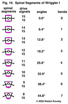
As shown in Fig. 19, the spectrum of balancing positions produced by linear opposing duets is modified and developed into a spectrum of balancing positions produced by a spinal segment. Force devices called movers operate in angular opposition in a spinal segment and perform the same functions as duets in the linear opposition design. Displacements in the linear system become bends in the angular system. Math-like features of the linear design carry over to the angular design.
Restrictions are imposed so that a smaller set of drive signals has one-to-one assignments to a smaller set of bends. As a result, each spinal segment can hold any of 15 bends; and numbers 1 through 7 are assigned for bends on each side. The set of bends includes midline represented by 0; seven bends left of midline, represented by –n; and seven bends right of midline, represented by +n. The set of 15 balancing positions can be represented by the 1 through 15 pulses in a burst of pulses.
|
|
|
|
|
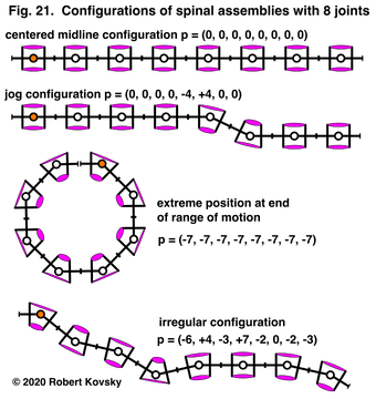
Spinal segments are assembled to make a spinal assembly. An 8-joint assembly illustrates collective features. The assembly can hold a set of configurations that are based on angular bends produced by various drive signals to the movers. A vector, such as the p's in Fig. 21, represents the sequence of bends of spinal segments in a configuration.
An orange dot in the joint of a terminal spinal segment marks the head of the spinal assembly and the first position in the p vector.
Each spinal segment operates independently of the others and there are some 2.5 billion possible configurations.
|
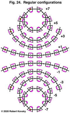
Fig. 24 shows a set of configurations that share a common feature: in any configuration, all the spinal segments have the same bend and bend-number. Such a set is called a family of configurations. Only odd-numbered members of the family are shown. This family is called "regular configurations" in recollection of "regular polyhedra" in geometry.
|
The eight configurations shown in Fig. 24 can be represented in a table or matrix as follows:
| +7 |
+7 |
+7 |
+7 |
+7 |
+7 |
+7 |
+7 |
| +5 |
+5 |
+5 |
+5 |
+5 |
+5 |
+5 |
+5 |
| +3 |
+3 |
+3 |
+3 |
+3 |
+3 |
+3 |
+3 |
| +1 |
+1 |
+1 |
+1 |
+1 |
+1 |
+1 |
+1 |
| –1 |
–1 |
–1 |
–1 |
–1 |
–1 |
–1 |
–1 |
| –3 |
–3 |
–3 |
–3 |
–3 |
–3 |
–3 |
–3 |
| –5 |
–5 |
–5 |
–5 |
–5 |
–5 |
–5 |
–5 |
| –7 |
–7 |
–7 |
–7 |
–7 |
–7 |
–7 |
–7 |
Next, suppose that the spinal assembly moves between successive positions. Perhaps the assembly starts in the +7 configuration. This means that drive signals (15, 8) are delivered to all eight spinal segments on a repetitive schedule. Then drive signals change to (15, 10) and the spinal assembly moves to the +5 configuration, where it rests for a short period. Then it moves to the +3 configuration, resting before moving to +1, to –1, to –3 and to –5, finally concluding the movements at –7.
The matrix becomes a script that represents the succession of movements.
Scripts in this project are restricted to movements where there is a period of rest between successive changes. Thus, movements are detached from one other. The initial movements of Wriggler I are slow; when signals change and new forces appear, spinal segments relax into new balancing positions.
|
|
|
3. An augmented spinal array performs locomotion scripts.
|
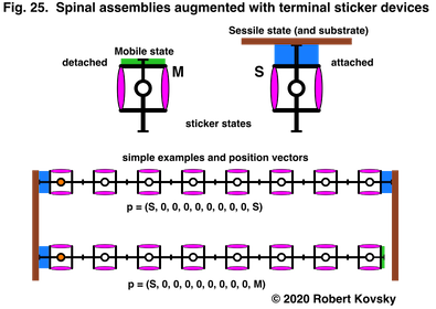
Fig. 25 shows sticker devices that are incorporated in the terminal segments of a spinal assembly. A sticker device has a mobile state (denoted by "M") and a sessile state (denoted by "S"). A sticker device in a sessile state is attached to a wall or substrate and maintains a perpendicular orientation with resistance against sideways forces. A sticker device in a mobile state is slick and does not attach or resist sideways forces.
The augmented spinal array is represented by an augmented p vector. "M" and "S" symbols at the ends of the vector represent the states of the sticker devices.
Changing the state of a sticker device, as indicated in Fig. 25, is treated as a kind of movement.
|
|
|
|
|
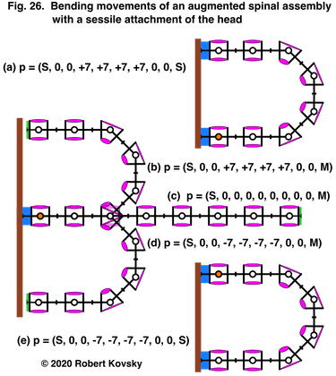
Fig. 26 shows a set of configurations where the head sticker device, the head segment and the second segment all stay the same while other segments move and the tail sticker device changes state. The figure also indicates a succession of movements, from configuration (a) to configuration (b), to (c), to (d) and to (e). And then perhaps in reverse order.
The first movement, from configuration (a) to (b), is performed by detaching the tail sticker device without any other movement. The movements from (b) to (c) and from (c) to (d) are large-scale movements where the spinal array straightens out and then bends to the other side. In the final movement, from (d) to (e), the tail sticker attaches to the wall.
Arch configurations can attach to a wall with sessile sticker devices at both ends. The generic form is p = (S, a, b, c, d, d, c, b, a, S), where a+b+c+d = +14 or –14, depending on the orientation of the assembly. The structure (a,b,c,d) is called a seed.
|
|
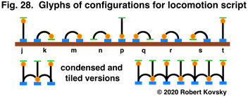
Successive symbolic glyphs in Fig. 28 make up a generic schema for a locomotion script. A glyph shows sticker states and spinal orientation of a configuration while disregarding details of seeds. In the generic script shown in Fig. 28, movement is to the right; the first and last positions share a midline configuration where the head is mobile and the tail is attached. This form allows for repetitive movements in the nature of tiles.
The generic locomotion script is represented in matrix form. Indices j, k, m, n, p, q, r, s, t connect positional glyphs with configuration vectors in the script. Here, a+b+c+d = +14 and w+x+y+z = –14.
|
|
Generic locomotion script
|
|
| M |
0 |
0 |
0 |
0 |
0 |
0 |
0 |
0 |
S |
| M |
a |
b |
c |
d |
d |
c |
b |
a |
S |
| S |
a |
b |
c |
d |
d |
c |
b |
a |
S |
| S |
a |
b |
c |
d |
d |
c |
b |
a |
M |
| S |
0 |
0 |
0 |
0 |
0 |
0 |
0 |
0 |
M |
| S |
w |
x |
y |
z |
z |
y |
x |
w |
M |
| S |
w |
x |
y |
z |
z |
y |
x |
w |
S |
| M |
w |
x |
y |
z |
z |
y |
x |
w |
S |
| M |
0 |
0 |
0 |
0 |
0 |
0 |
0 |
0 |
S |
|
|
4. The spinal driver module drives scripted locomotion movements of the spinal assembly.
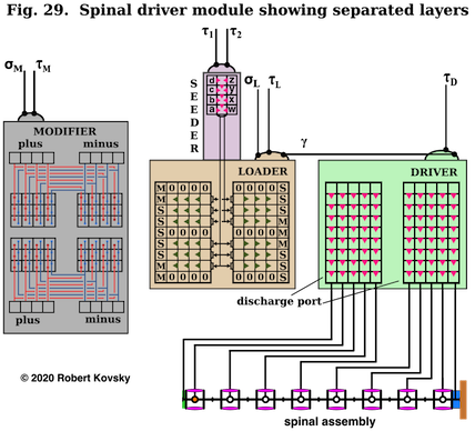
Fig. 29 shows the spinal driver module that generates locomotion scripts and uses them to drive the spinal assembly. The module has four chief device parts shown in colored blocs and labeled Loader, Driver, Seeder and Modifier. These quadnet devices are made of many smaller individual devices (shown as boxes in the figure) that are similar to the repeating bursters in Fig. 7 above but that also have collective operations triggered by pulses through σ and τ projections.
The spinal driver module is shown in Fig. 29 with layers separated and spread out. When layers are assembled, individual burster devices in Loader fit on top of corresponding burster devices in Driver. Corresponding individual burster devices in Modifier and Loader likewise fit together. Operations occur inside each layer and between layers.
A whole locomotion script is held in the quadnet area of Loader and transferred to Driver. Fixed values in Loader bursters (0, M, S) are the same in every locomotion script. Variable values in locomotion scripts are specified by seeds. Values in seeded areas of Loader can be transferred to Modifier. When a script is held in Loader and transferred to Driver and/or Modifier, the first or initial configuration in the script is at the bottom of the device (close to the spinal assembly) and the last configuration is at the top of the device.
After a a script has been transferred to Driver, the researcher sends a pulse through the τD projection to Driver, which triggers operations that send signals through the discharge port of Driver to the spinal assembly, causing it to hold the first configuration of the script. Triggered by successive τD pulses, rows of the script advance through Driver and sequentially drive the spinal assembly in locomotion movements.
To get a new script into Loader, the researcher prepares seeds denoted as (a,b,c,d) and (w,x,y,z) in Seeder and triggers their propagation through the central channel in Loader. This channel distinguishes the head half of the spinal assembly from the tail half. It is replicated in other quadnet devices but does not affect movements.
|
|
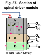
Another way to get new scripts into Loader is by use of Modifier. Fig. 37 shows a representational section of the assembled spinal driver module with a variety of connectors between devices. (Connectors include projections, receptors and triangular junctions). Loader, Driver and Modifier have the same colors as in Fig. 29.
Fig. 37 shows a module of Modifier that has four burster devices, (I)nput, (O)utput, (A)djustment and Re(V)ersal. Following a command, Loader transfers seed values to Input bursters of Modifier, which automatically transfers them to Adjustment bursters and Reversal bursters, where values are modified. The researcher can transfer modified seed values from either Adjustment bursters or Reversal bursters through Output burster to Loader. Loader then holds a modified script.
Seed values can be increased or decreased in Adjustment bursters; resulting locomotion scripts generated in Loader have wider or narrower arches.
Seed values are switched from left to right in Reversal bursters (and from right to left). That is, a seed value –n when sent from Loader to Modifier becomes +n when sent from Reversal bursters to Output bursters to Loader. An original midline value 0 stays at 0 in the reversal script.
Suppose that an original script is transferred from Loader to both Driver and Modifier. While the original script is running in Driver, the reversal script is held in Reversal bursters. If the reversal script is transferred to Loader and run though Driver after the original script is finished, the spinal assembly will return to the place on the wall that was occupied before the original script started.
|
... top of page
- Available for download:
- ... Wriggler I: an engineered organism (2020) (in .pdf format, 2.8 Mb).
... Metamorphosis of Wriggler I (2021) (in .pdf format, 1.3 Mb)
... Wavy movements in a hybrid domain of classical and Virtual Energy devices (2022) (in .pdf format, 3.3 Mb)
... Reconstruction of the Wriggler I system for quicker, more compact operations (2022)
- Other links:
- ( ... ) opening page of the quadnets website;
- ( ... ) sitemap and organized table of contents for the website.
January 2020, December 2021, April 2022, June 2022
Copyright © 2020, 2021, 2022 Robert Kovsky